Project Overview
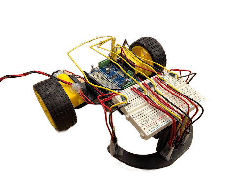
This project integrated sensing and control with a two-wheeled robotic platform to autonomously follow a taped track on the floor. The system uses a closed-loop PD controller on an Arduino that can navigate a non-circular loop course. A key requirement was the ability to tune the controller and adjust robot performance in real-time via serial communication, without recompiling code, to achieve the fastest possible run times.
Design Approach
We designed a custom chassis to precisely control wheel-to-wheel distances, sensor placements and heights, and other design elements that would optimize our code's performance. We implemented a proportional-derivative (PD) control scheme using five infrared sensors:
- Three center sensors: Positioned close together for main line following
- Two outer sensors: Positioned further out and less far forward for sharp corner detection
The control algorithm stays centered on the line using the main sensors, only using the far sensors when the main sensors lose sight of the line. This approach enabled fast line following with consistent sharp corner navigation.
Mechanical Design
Chassis Configuration
Our mechanical design focused on creating a stable, balanced platform. We positioned the motors and wheels in the back to maximize sensor turning radius and concentrate weight over the drive wheels for better traction. The chassis measures 5 inches wide by 6.5 inches long and uses a three-point contact system:
- Two driven wheels in the back for propulsion
- One caster wheel in the front for balance
- Sloped design to accommodate caster wheel without interference
- Adjustable sensor height using caster wheel spacers
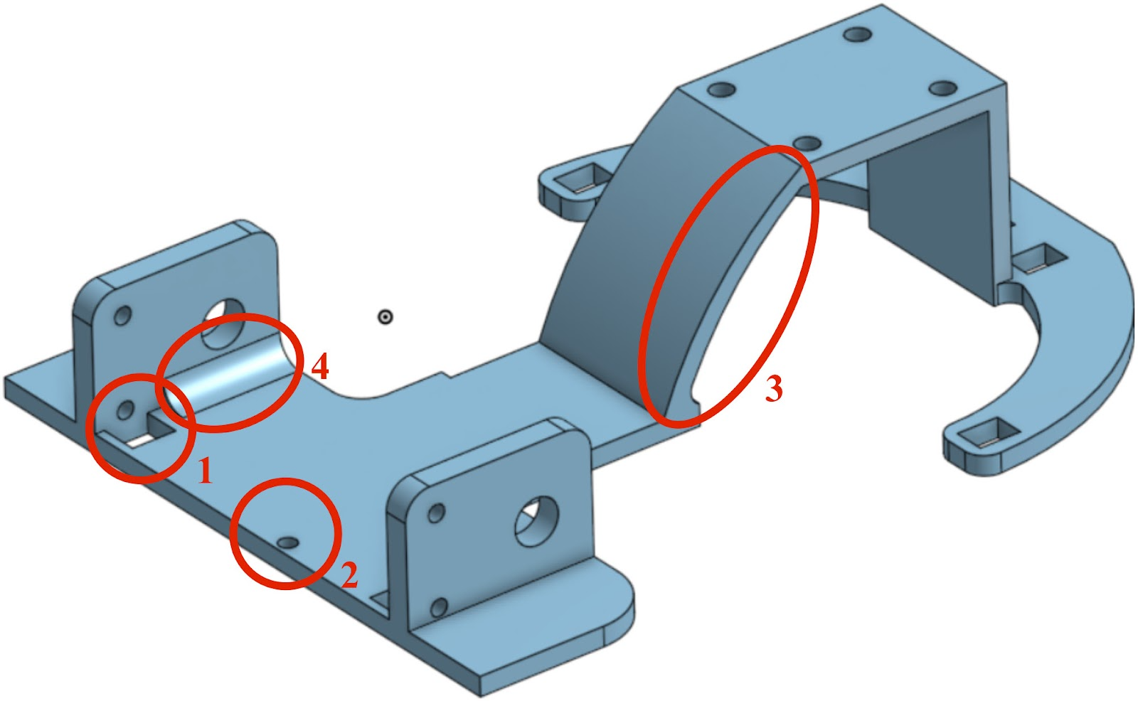
Chassis Design Features
- Location 1 - Motor Nut Clearance: Hole to allow spacing for the nut that attaches to the screw holding the motor
- Location 2 - Arduino Mounting: Mounting hole for attaching the Arduino and motor shield to the chassis using a screw
- Location 3 - Caster Wheel Slope: Sloped design to give room for the caster wheel without hitting the chassis (only needed on the front since the robot moves forward)
- Location 4 - Reinforced Motor Mounts: Thick motor mounts chamfered to the base for additional structural support
All design choices were based on precise measurements of physical components using a caliper, with appropriate tolerances for assembly.
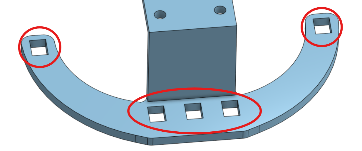
Sensor Array Evolution
Initially, we used three sensors positioned close together in the center. However, this design failed at sharp turns greater than 90 degrees because the sensors couldn't see the line during tight corners. To solve this, we added one sensor on each side, positioned slightly further back, to detect the line when the center sensors lost contact.
The sensors were positioned with 8mm spacing between the three center sensors - slightly wider than the tape. This made programming easier: when perfectly following the line, the middle sensor sees full tape color while the side sensors only partially see the line.
Electronic Design
Component Specifications
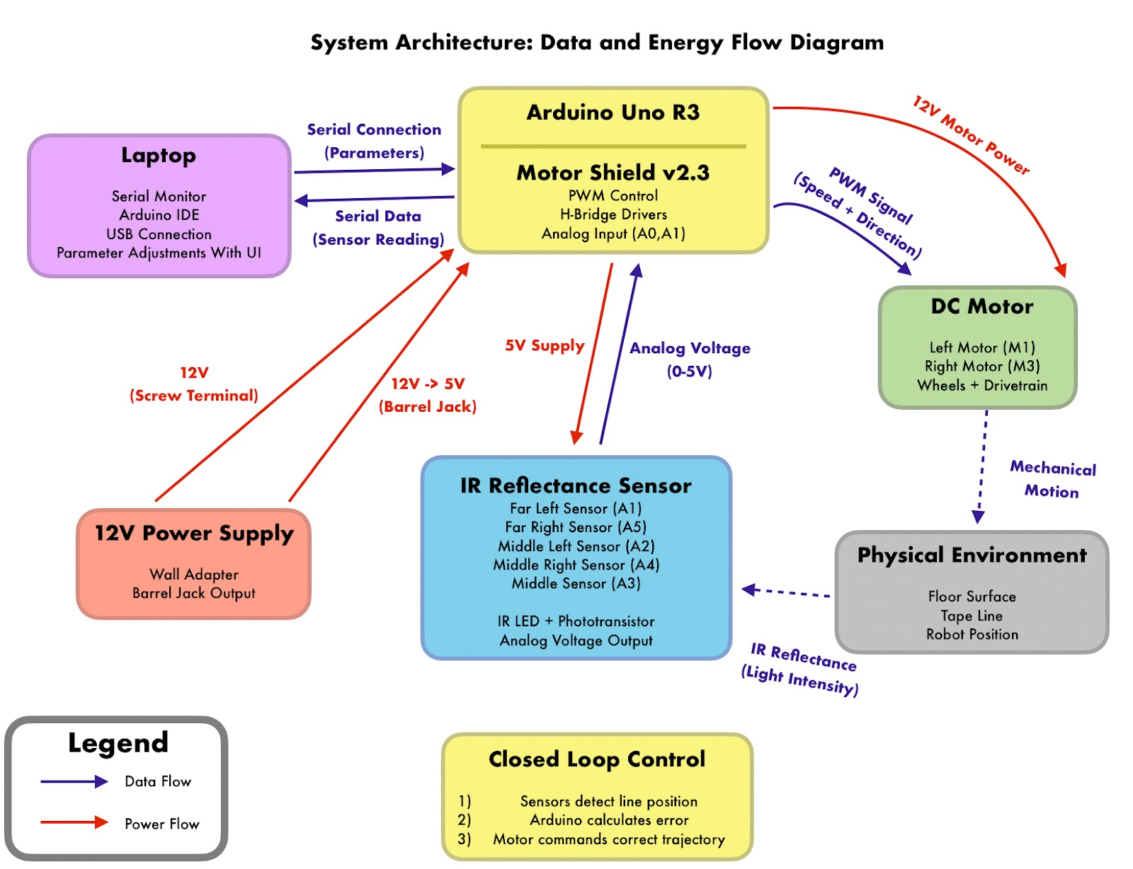
- Infrared Sensors: TCRT5000 with analog voltage output (0-5V)
- Motors: 3-7.2V DC gearmotors, 210 RPM, 48:1 gear ratio, driven at 12V
- Microcontroller: Arduino Uno with ATmega328P
- Motor Control: Adafruit Motor Shield v2.3 with PWM speed control
- Power: 12V wall adapter split between Arduino and Motor Shield
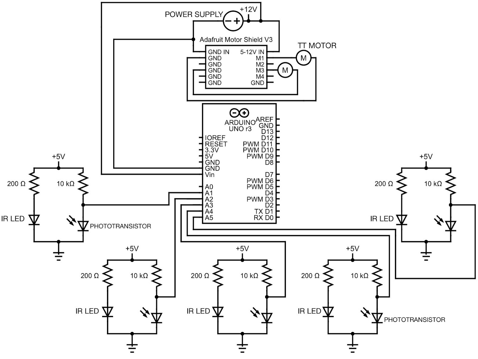
Sensor Circuit
Each IR reflectance sensor includes:
- IR LED with 200Ω current-limiting resistor (~15mA current)
- Phototransistor with 10kΩ pull-up resistor
- Analog voltage output proportional to surface reflectivity
Control System Design
PD Control Algorithm
We implemented a Finite State Machine (FSM) with two primary states:
- PD Control State: Active when center sensors detect the line
- Line Search State: Active when center sensors lose the line, uses outer sensors to reacquire
The PD controller calculates an error signal and applies proportional and derivative corrections:
ERROR = (LEFT_READING - RIGHT_READING)
CORRECTION = Kp * ERROR + Kd * (ERROR - LAST_ERROR)
LEFT_SPEED = BASE_SPEED + CORRECTION
RIGHT_SPEED = BASE_SPEED - CORRECTION
Tuned Parameters
- Kp (Proportional Gain): 10 - provides immediate response to error
- Kd (Derivative Gain): 15 - provides damping to reduce oscillation
- Base Speed: 50 (0-255 PWM range)
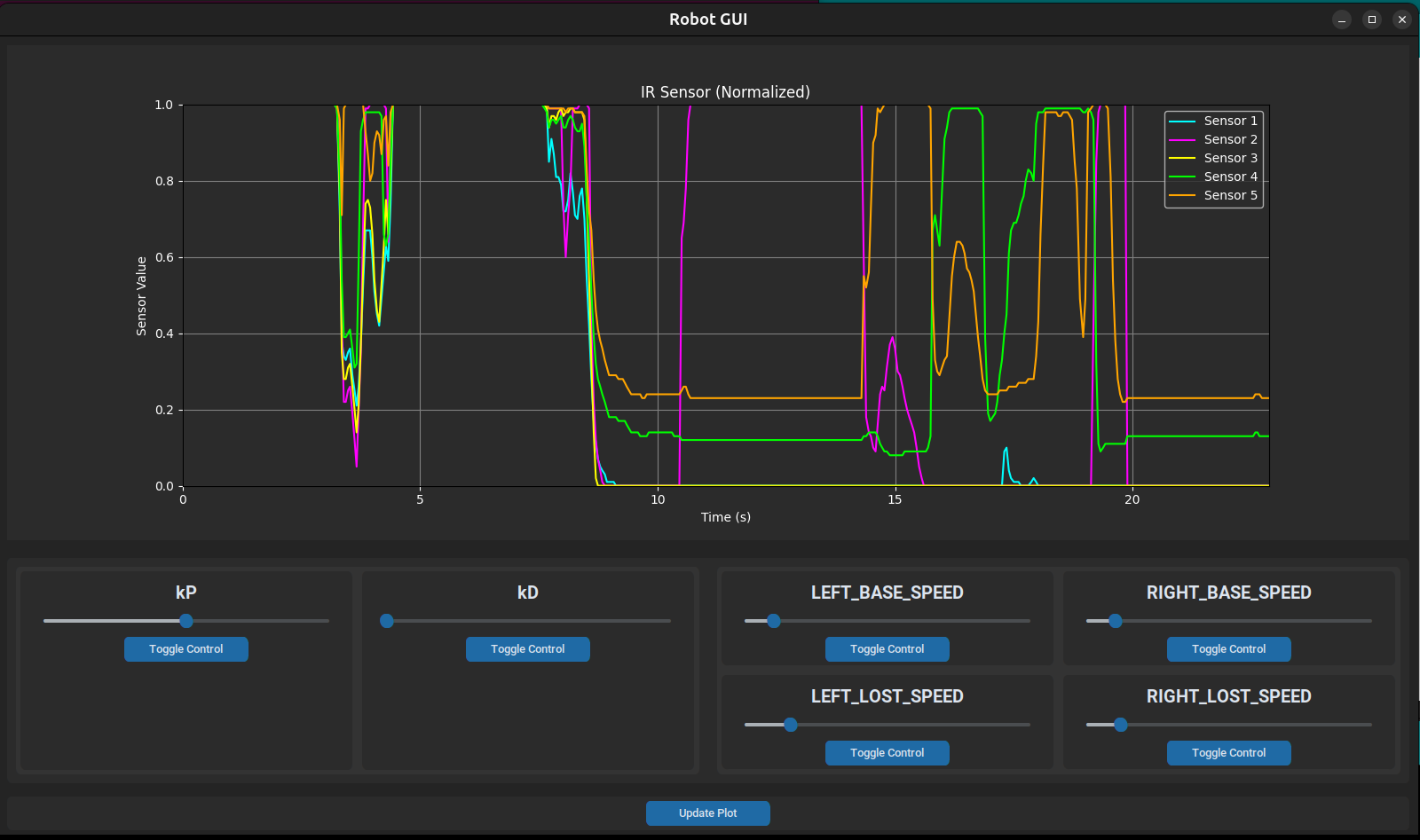
Real-Time Parameter Tuning
We created a Python GUI with serial communication that enabled runtime parameter adjustment without code recompilation. The interface features:
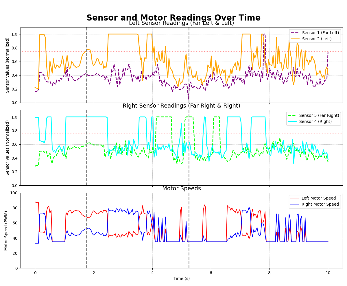
- Real-time normalized IR sensor readings plotted over time
- Adjustable sliders for Kp, Kd, and motor speeds
- Bidirectional serial protocol for sending commands and receiving sensor data
This dramatically accelerated the tuning process, allowing us to optimize performance through rapid iteration.
Performance Results
- Best Lap Time: 30 seconds
- Success Rate: 15/15 attempts (100%)
- Sensor Calibration: Highly reliable across different surfaces
- Sharp Corner Handling: Successfully navigates turns >90 degrees
Challenges Overcome
Challenge 1: Sharp Corners
Problem: Sharp corners (especially the "armpit") caused the 3-sensor design to lose the line.
Solution: Added 2 outer sensors and implemented FSM to detect and correct for line loss.
Challenge 2: Prototype Iteration
Problem: Initial solderable breadboard made component changes difficult.
Solution: Switched to solderless breadboard for rapid prototyping, then planned PCB for final version.
Challenge 3: Parameter Tuning Speed
Problem: Recompiling and re-uploading code for each tuning adjustment was time-consuming.
Solution: Developed Python GUI with serial communication for real-time parameter adjustment.
Key Learnings
- Calibration is Critical: Thorough sensor calibration resulted in reliable operation
- Iterative Design: Rapid chassis iteration enabled optimization of sensor locations
- Real-Time Tools: GUI dramatically improved tuning efficiency over code recompilation
- State Machines: FSM approach cleanly separated normal operation from corner handling
Technical Specifications
- Dimensions: 5" W × 6.5" L chassis
- Sensors: 5× TCRT5000 IR reflectance sensors
- Sensor Height: 5mm above ground (optimized via testing)
- Sensor Spacing: 8mm between center sensors
- Motors: 2× DC gearmotors, 210 RPM, 48:1 ratio
- Control Frequency: ~100 Hz (10ms loop time)
- Power: 12V DC supply