
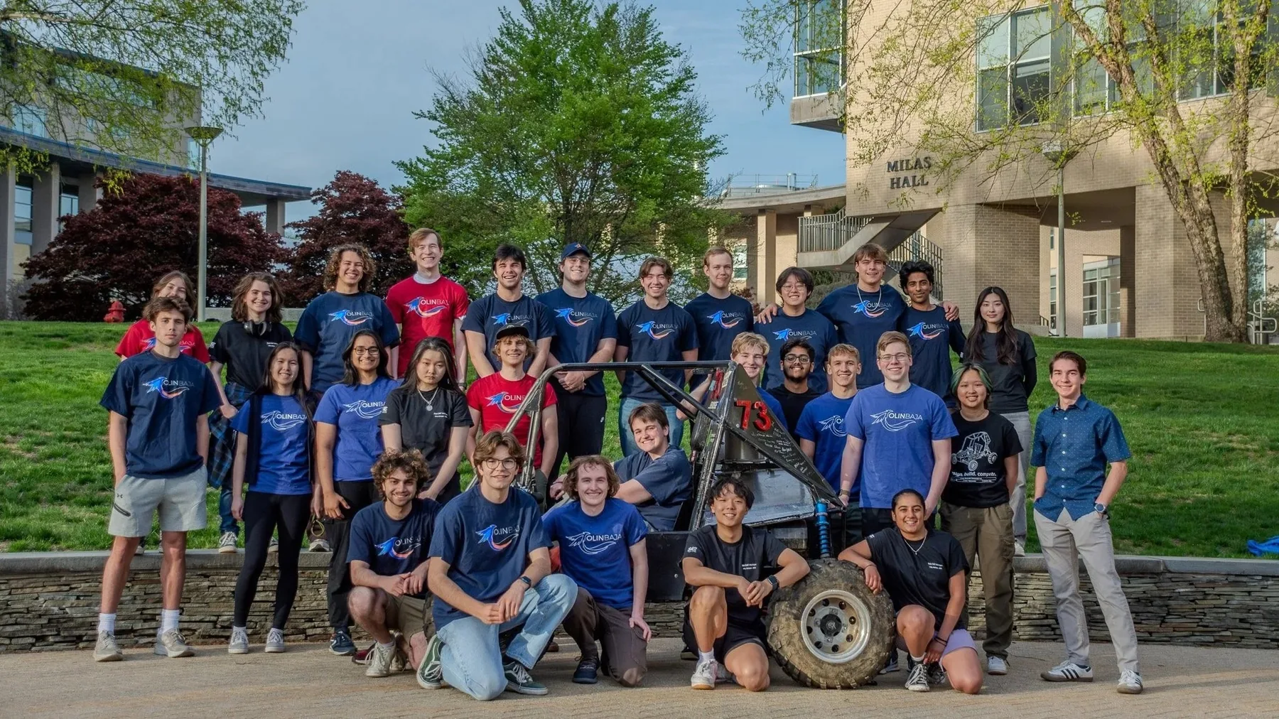
I have been Chassis Lead on Olin's Baja SAE team for over a year, since my sophomore year. I own the design, fabrication and assembly of the tubular space frame: the SolidWorks model, the ANSYS FEA, the bill of materials, the welding jigs and most of the TIG welding. The new chassis is 15% lighter than the old one at the same strength, and we compete in September 2026.
Overview
Baja SAE teams design, build and race a single-seat off-road vehicle. Events test acceleration, maneuverability, hill climbing and a 4-hour endurance race, and the car has to survive jumps, mud, rocks and repeated impacts while staying fast and reliable. We compete in September 2026 against universities from across the country in endurance, maneuverability and hill-climb events.
As Chassis Lead I also train new members on welding and fabrication and coordinate mounting points and clearances with the suspension, powertrain and controls teams.
- Design: lead the CAD of the tubular space-frame chassis in SolidWorks, checking it against the SAE rules and against every other subsystem.
- Fabrication: coordinate TIG and MIG welding, jig design and tube cutting.
- Bill of materials: manage the chassis BOM, order all tubes and materials, and cross-check specifications against the SAE rulebook.
- Onboarding: train new members in welding, fabrication, safety and design for manufacturing.
- Integration: agree mounting points and clearances with the suspension, powertrain and controls teams.
- Analysis: run ANSYS FEA to validate chassis strength, find high-stress areas and size tubes.
Design
The chassis is a tubular space frame modelled in SolidWorks and checked in ANSYS. The current design is a rework of the previous chassis around the driver, the engine and the suspension.
Structural analysis
I run finite element analysis in ANSYS to check chassis strength and cut weight. The simulations cover the worst-case loads: jumps, side impacts and rollovers.
The results show where gussets or larger-diameter tubes are needed and where material can come out. That is how the chassis lost weight without losing strength.
Cockpit and driver safety
I redesigned the cockpit section for driver ergonomics while keeping the rollover protection:
- Lower seat position, for center of gravity and driver visibility.
- Adjustable pedal box for drivers of different heights.
- Reinforced roll hoop with side-impact protection beyond the SAE requirement.
- More ingress/egress clearance for faster driver changes during endurance.
Engine integration and serviceability
With the powertrain team I reworked the engine mounting and maintenance access:
- Removable engine-bay panels for quick CVT belt changes at competition.
- Vibration-isolated engine mounts to reduce fatigue on the chassis and components.
- Enough clearance between tubes for a worst-case engine swap.
Suspension geometry and clearance
With the suspension team I moved the A-arm mounting points and made room for more wheel travel:
- Relocated suspension pickup points for anti-dive and anti-squat.
- Wheel travel increased from 8" to 10".
- Clearance for full suspension droop on jumps and rough terrain.
- Shock-mounting tabs integrated into the chassis tubes to save weight.
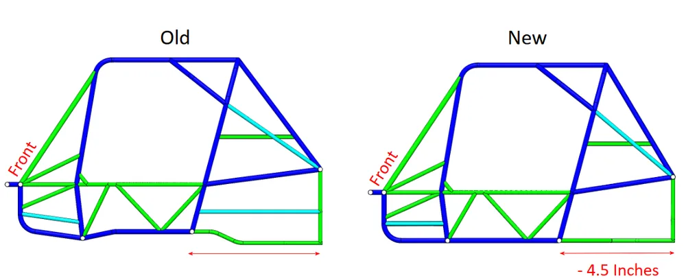
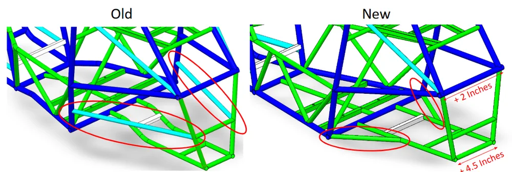
Old versus new chassis
The previous chassis compared with the current design.
Build
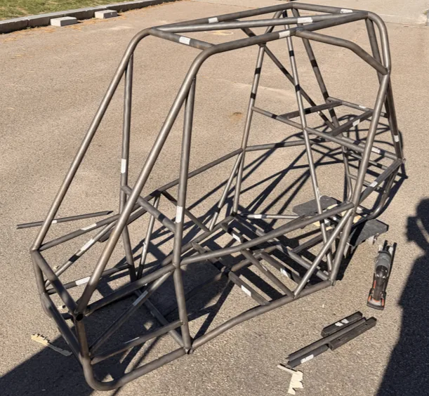
The frame is TIG welded from thin-wall AISI 1018 steel tubing. Getting the welded geometry to match the CAD comes down to the tube order, the jigs and checking each joint.
Bill of materials
I keep the bill of materials for the chassis so every tube meets the SAE specification and arrives on schedule.
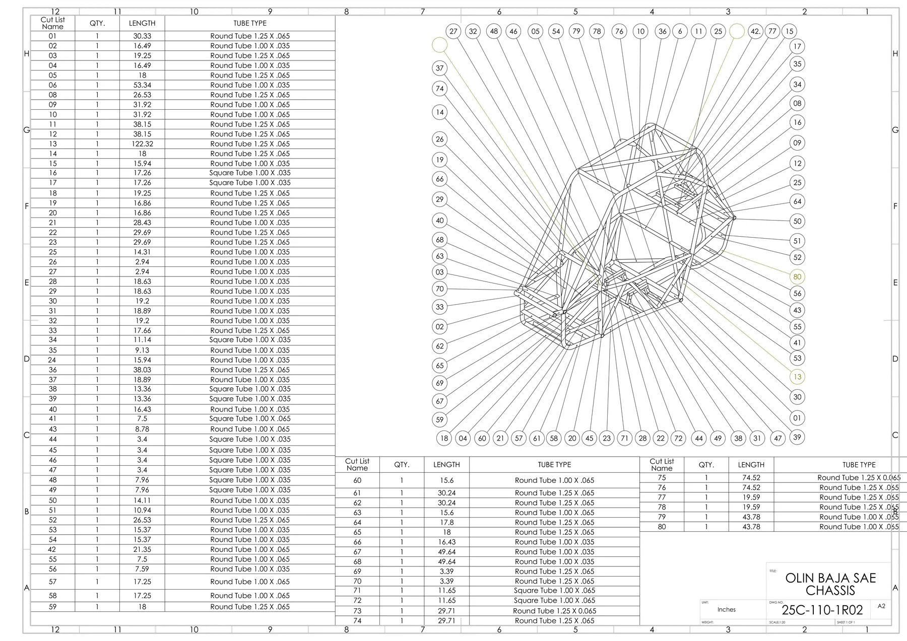
The BOM lists material grade, wall thickness, outer diameter and length for every tube, each cross-referenced to the SAE rulebook. I order from VR3 Tubes and other suppliers, track deliveries and check the material on receipt.
Welding jigs
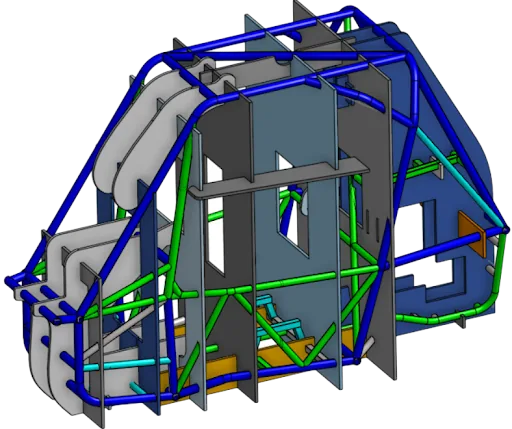
I designed laser-cut sheet jigs that hold the tubes in alignment during tack welding and final welding. Without them the frame geometry drifts away from the model as the welds pull.
TIG welding
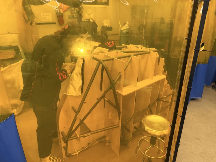
All primary structural joints are TIG welded for penetration. On thin-wall 1018 tubing that means managing heat input, filler-rod technique and inspecting every weld afterwards.
- Tungsten selection and electrode grinding for penetration control.
- Back-purging to prevent oxidation inside the tube.
- Heat-input management to limit warping and preserve material properties.
- Filler-rod selection and technique for full-penetration welds.
- Visual inspection and dye-penetrant testing on the welds.
Testing
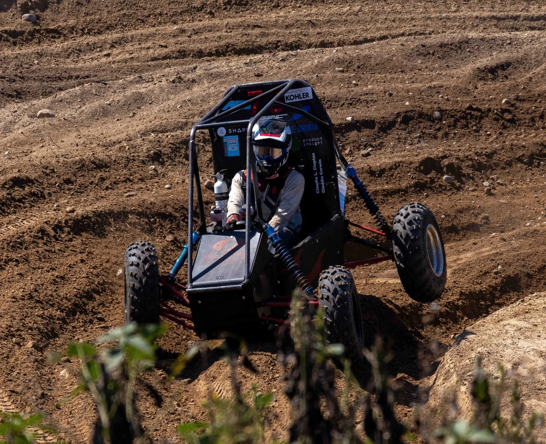
Driving the car on rough terrain to check the chassis and the suspension integration.
Results
- Engine-bay access panels made the car easier to service.
- Standardized jig designs improved fabrication accuracy and speed.
Before
The team is in the last stretch before the September 2026 competition. What is left:
- Finish chassis fabrication and final welding.
- Integrate all subsystems and assemble the full vehicle.
- Test until it is reliable under competition conditions.
- Write the technical documentation and design reports for the judges.
- Train drivers and practice quick repairs for endurance-race pit stops.
- Finalize the spare-parts inventory and competition logistics.
What I learned
Leading chassis design and fabrication taught me design for manufacturing: a design has to be buildable with the equipment and the people we actually have. If the team cannot fabricate it accurately and repeatably, the CAD does not matter.
Working with new members showed me how much knowledge leaves with each graduating class. Writing down processes, making training material and mentoring newcomers is how the team's knowledge grows each year instead of resetting.
The loop of CAD, simulation, fabrication, testing and revision shows how engineering decisions play out in the real thing. When the chassis survives a hard test it confirms the analysis; when something fails it tells us what to change next.
Skills
- Welding: TIG on AISI 1018 steel tubing, MIG on mild steel, heat management, back-purging.
- CAD: SolidWorks assemblies, weldments and fabrication drawings.
- Analysis: ANSYS FEA for stress, fatigue life and weight reduction.
- Manufacturing: tube notching, jig and fixture design, quality control, design for manufacturing.
- Project management: bill of materials, supplier coordination, scheduling.
- Rules: reading the Baja SAE rulebook and checking the design against it.
- Teaching: training new members and coordinating work across subsystems.